查看更多福禄克品牌

Overview of 8588A and 8558A calibration support processes and equipment requirements
Document(s):
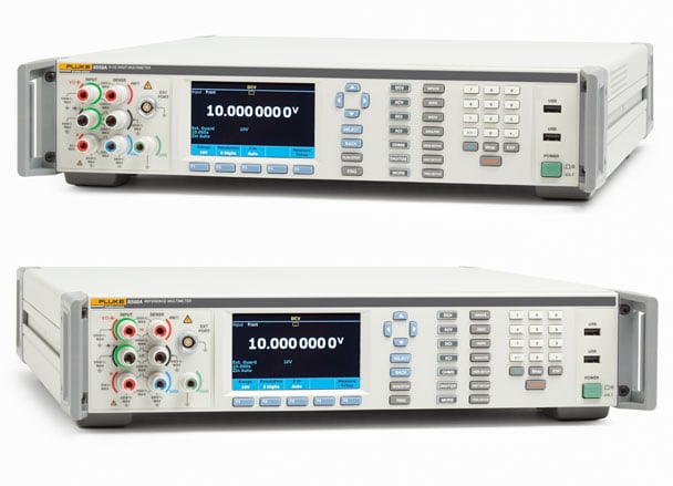
The Fluke Calibration 8588A Reference Multimeter and 8558A 8.5-Digit Multimeter are class leading 8.5-digit precision multimeter instruments featuring superior accuracy and long-term stability over a wide measurement range, with an intuitive user interface and a color display.
With more than 12 measurement functions, including the new digitize voltage, digitize current, capacitance, RF power, and external shunts for dc and ac current, the 8588A helps you consolidate your lab’s cost of test into a single measurement instrument. Its superb analog performance is augmented by Fluke Calibration’s new high-speed system design and the industry’s fastest direct digitizing capability, enabling significant throughput increase for many automated systems demanding a combination of the highest speed and best accuracy. Both models share the majority of calibration processes and support requirements, with some differences due to differing performance and functionality between the models. This application note provides an introductory overview of these calibration adjustment and performance verification processes; together with recommended calibration equipment requirements based on those used in the Fluke factory and service centers, and as described in detail in the instrument service manuals.
Product specifications and calibration uncertainties
At the Fluke factory and service centers both 8588A and 8558A are calibrated and performance is verified on the same calibration systems with essentially identical calibration uncertainties. Those calibration systems, supporting traceability and metrology processes and resulting calibration uncertainties, must meet the most demanding requirements for the higher performance 8588A model. Because the lower performance 8558A model is calibrated and verified on the same system, the same system related uncertainties are applied to both models. Therefore, the difference between corresponding absolute and relative specifications is similar for each model, as evidenced in Table 1. For example: see 0.1 µV/V of reading for the dc voltage function 10 V range at 95 % confidence level. Note that the stated absolute uncertainty is the RSS rootsum-square combination of relative uncertainty specification and applicable calibration uncertainty (converted to the same confidence level), and that the applicable calibration uncertainty also includes the effect of the device under test (DUT). Thus, simply considering the arithmetic relative/absolute differences in Table 1 may not in all cases give identical results for each model.
Depending on application needs, some 8558A users may only be concerned with relative specifications or may tolerate wider absolute specifications. Therefore, these users may choose to trade off wider calibration uncertainties for simpler or cheaper calibration standards support processes, or to use external calibration providers not able to offer such tight uncertainties.
Table 1. 8588A and 8558A Key Specifications Comparison
| Function | 8588A ± (µX/X of reading + µX/X of range) |
8558A ± (µX/X of reading + µX/X of range) |
||||
| 95% | 99% | 95% | 99% | |||
| DC voltage | 10 V | Relative | 2.7 + 0.05 | 3.5 + 0.06 | 4.0 + 0.06 | 5.2 + 0.08 |
| Absolute | 2.8 + 0.05 | 3.6 + 0.06 | 4.1 + 0.06 | 5.3 + 0.08 | ||
| AC voltage | 10 V, 1 kHz | Relative | 60 + 5 | 77 + 6.5 | 80 + 10 | 103 + 13 |
| Absolute | 64 + 5 | 83 + 6.5 | 90 + 10 | 116 + 13 | ||
| Resistance | 10 kΩ | Relative | 7 + 0.5 | 9 + 0.6 | 10 + 0.6 | 13 + 0.7 |
| Absolute | 7.2 + 0.5 | 9.2 + 0.6 | 10 + 0.6 | 13 + 0.7 | ||
| DC current | 10 mA | Relative | 8 + 4 | 10 + 5 | 10 + 5 | 13 + 6 |
| Absolute | 8.9 + 4 | 11 + 5 | 11 + 5 | 14 + 6 | ||
| AC current | 10 mA, 1 kHz | Relative | 250 + 50 | 323 + 62 | 300 + 100 | 387 + 129 |
| Absolute | 260 + 50 | 335 + 65 | 310 + 100 | 400 + 129 | ||
| Frequency | BNC, 1 kHz | Relative | 0.5 uHz/Hz | 0.5 uHz/Hz | 0.5 uHz/Hz | 0.5 uHz/Hz |
| Temperature | PRT 100 Ω Type K, S, J, B, R, E, L, U, C, N*, T* | Relative | ± 5 mK | ± 5 mK | ± 5 mK | ± 5 mK |
| Capacitance | 1 uF | Relative | 400 + 100 | 516 + 129 | N/A | N/A |
| Absolute | 400 + 100 | 516 + 129 | N/A | N/A | ||
95 % and 99 % 1 year relative accuracy specification. Fluke Calibration guarantees to specification at 99 % confidence interval k=2.58.
*Types N and T are ± 5 mK for ≥ 120 K (-123C)
Calibration architecture and adjustment process
In common with most modern test and measurement instruments, the 8588A and 8558A multimeters employ entirely digital alignment and calibration adjustment mechanisms, storing calibration correction factor data in internal nonvolatile memory. Both multimeter models have two sets of calibration correction stores; named Certified and Baseline. The Certified corrections are copied to the Baseline stores during factory calibration. The products leave the factory with Certified stores active and the accompanying calibration certificate refers to performance in this configuration. Baseline stores would normally only be overwritten after repair. At routine recalibrations (annual or biannual, etc.) only the Certified stores are updated; the Baseline is not changed. This enables users and metrologists to employ the Baseline corrections to monitor long-term drift of the multimeter unaffected by the changes to the Certified stores from routine calibration adjustment. Also, one can prove that the multimeter performance was unaffected by transit to and from routine calibration events or transit to and from locations where it is used as a standard to calibrate and certify other equipment.
Calibration adjustment involves a limited sequence of points (functions and ranges) at which the multimeter is adjusted directly against external traceable standards. On completion of the adjustment sequence, and making use of the correction data obtained, the remaining functions and ranges are automatically adjusted by internal transfers controlled by the instrument. For example, the capacitance function obtains capacitance readings from the relationship between capacitance and voltage dV/dt measured under constant current charging conditions. Except for the 1 nF range, calibration data for capacitance ranges are derived internally from the calibration data obtained during adjustment of the resistance function current sources, the relevant dc V measurement ranges and the internal master frequency reference. Note that the calibration adjustment sequence must be completed with all required adjustment points adjusted, otherwise some functions and ranges will be left in an un-adjusted state The calibration adjustment process may be carried out manually via the front panel, or under computer control via the remote interface(s). When executed manually, the multimeter leads the user through the adjustment point sequence, prompting for application of the necessary input. When the sequence is completed and correction data is stored, the multimeter is fully calibrated, with measurement performance meeting specification on all ranges and functions. However, to demonstrate traceability for all functions and ranges, the multimeter must also be measured at the recommended performance verification test points on all functions against traceably calibrated standards.
The factory and service center automated calibration systems use the multimeter remote interface. For users with appropriate equipment and capability wishing to perform their own calibrations, the 8588A and 8558A Service Manual contains full details of the equipment required, measurement points and step-by-step instructions duplicating the factory procedures for calibration adjustment and performance verification.
Calibration standards requirements and recommended equipment
A summary of the recommended calibration standards equipment items for 8588A and 8558A calibration and verification is listed in Table 2. To achieve the required low uncertainties, the equipment must be traceably characterized to determine actual output values at the required measurement points. This data is used to correct for error from nominal of the calibration stimulus applied during the multimeter calibration adjustment and performance verification processes, achieving uncertainties much smaller than published equipment specifications would otherwise suggest. Full details of the equipment requirements (sufficient to allow substitution of appropriate alternatives), adjustment and verification points appear in the 8588A and 8558A Service Manual.
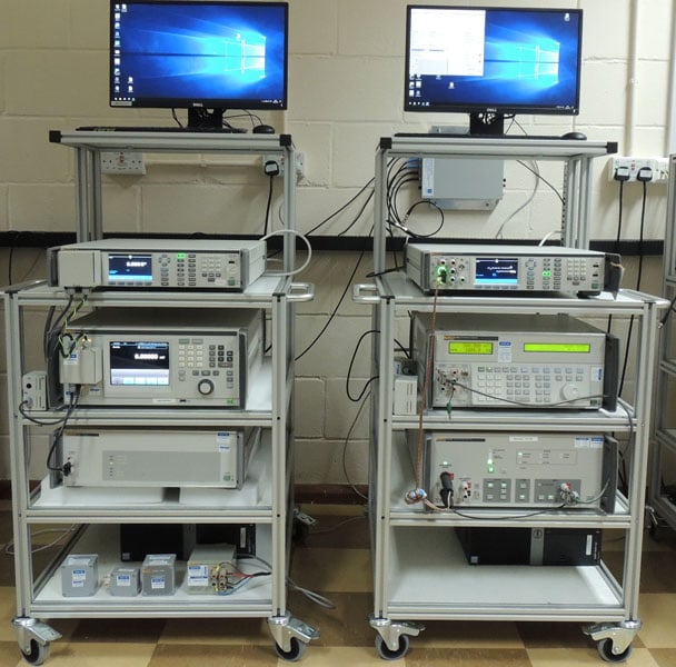
Table 2 shows that some equipment is not required for calibration adjustment, used only for performance verification. Therefore, in practice, it is convenient to arrange the equipment in two groups or systems, corresponding to adjustment plus verification and verification only usage. The factory calibration systems are arranged in this manner, shown in the photograph with adjust/ verify part one on the left and verify part two on the right.
Table 2. 8588A and 8558A recommended calibration equipment summary
| Item | 8588A | 8558A | Calibration Adjustment | Performance Verification | Functions/Parameters calibrated/verified |
| 5730A Calibrator | ● | ● | ● | ● | DC V, AC V, Resistance, DCI , AC I, Digitize DC V and DC I |
| 5725A Amplifier | ● | ● | ● | ● | High Voltage AC V, DC I up to 10 A, AC I |
| 5522A Calibrator [1] | ● | ● | ● | Counter, Capacitance | |
| 52120A Amplifier | ● | ● | DC I and AC I at 30 A | ||
| 742A 1 Ω Standard | ● | ● | ● | ● | Resistance |
| 1 GΩ Standard [2] | ● | ● | ● | ● | Resistance |
| Ohm Lab 110 10 GΩ Standard [3] | ● | ● | ● | Resistance | |
| IET Labs/GR 1403-A 1000pF Air Capacitor [4] | ● | ● | Capacitance | ||
| 10 MHz Frequency [5] Standard | ● | ● | ● | ● | Counter |
| [1] Fitted with any oscilloscope calibration option, for counter function verification up to 100 MHz [2] Part of 8588A-7000K Cal Kit [3] Optional Equipment. See text for explanation. [4] Or low frequency characterized silver mica/fused silica device [5] Also used as 5522A External Frequency Reference |
|||||
Performance verification points used in the Fluke factory and service center calibration systems, and data appearing in the calibration certificates delivered from the factory, include additional points beyond the minimum needed to traceably confirm complete and correct adjustment of all functions and ranges following the calibration adjustment process outlined above. These additional points provide extra information some users may find helpful and informative. They are not essential and may be optionally omitted, reducing the calibration time, support complexity and costs. The Service Manual calibration procedure includes and identifies these additional ‘optional’ points. For example, measurement at 10 GΩ, hence noting the 10 GΩ standard resistor in Table 2 as optional equipment.
8588A and 8558A calibration and performance verification compared to 8508A
Calibration support requirements for the 8588A and 8558A models are similar to those for the predecessor 8508A Reference Multimeter. Users and metrologists familiar with 8508A support will recognize the similarity in recommended calibration equipment between the 8508A (characterized 5720A and 5725A, 1 GΩ Standard, etc.) and the list in Table 2. The need for additional equipment is due to the expanded features and capabilities of the 8588A and 8558A.
However, compared to 8508A, the 8588A and 8558A have entirely different design architecture, circuitry, internal construction and calibration adjustment mechanisms. Despite the greater functionality, the 8588A and 8558A have approximately one third of the number of calibration adjustment points compared to 8508A. This significant improvement is made by the adjustment/alignment processes common to both 8588A and 8558A avoiding the duplication inherent in the 8508A, where all ranges are individually adjusted.
If all the recommended points are tested, full verification of the 8588A requires approximately 600 points (fewer for the 8558A), around 2.5 times as many compared to 8508A. Despite the points count differences, the overall calibration adjustment and verification times for the 8588A and 8558A are similar to the 8508A. However, the number of essential 8588A and 8558A verification points is less when the optional points are discounted. These essential verification points are those necessary to confirm full and correct completion of the adjustment and internal alignment processes and specification compliance. They also confirm traceability and include the typical cardinal points at which users and metrologists expect to see data in a calibration certificate and often rely on to establish their own traceability and uncertainty budgets.
The verification points listed in the recommended procedures in the 8588A and 8558A Service Manual are chosen based on the multimeter hardware design architecture, component and circuit characteristics, and calibration adjustment processes—including the internal alignment phase (calibration data derivation) that takes place automatically on completion of adjustments made against external traceable standards and calibration stimuli. Likewise, the inclusion and selection of points listed as optional.
Consider the following example of optional points: The recommended verification procedure includes measurement of all ranges at 1x range and optionally at 2x range. Depending on their application needs, measurement capabilities, policies and attitudes, etc., some users and metrologists may choose to retain the 1x and 2x on the primary ranges but omit all other 2x points in favour of faster process times and lower support costs, etc.
Similarly, some users and metrologists may choose to omit any other points listed as optional. Omitting all optional points significantly reduces points count, by around 20 %. The result is overall calibration adjustment and verification (certification) time reduction in comparison to 8508A.
Summary
In summary, customers and users with appropriate equipment, traceability and metrological capabilities can self-support, calibrate and certify the superior performance and functionalities of the 8588A and 8558A multimeters. Please refer to the the 8588A and 8558A Service Manual for full equipment and procedure details. Go to the Fluke Calibration website for further 8588A and 8558A product information, precision DMM calibration information, application notes and on-demand web-seminars.
 在线客服
在线客服