查看更多福禄克品牌

Understanding specifications of DC reference standards
Introduction
The Fluke Calibration 732C / 734C DC Reference Standard is the third generation of lab quality electronic reference standards first pioneered by Fluke. The direct voltage reference is used to maintain traceability to national standards and to distribute the volt to production, service, calibration laboratories or other remote locations. It has been designed specifically for metrologists. Not only does it provide the performance metrologists need, but it is specified in ways to allow users to really understand the uncertainties of the measurements, and easily make allowance for compiling uncertainty budgets. Contemporary metrology practices, including ISO/IEC17025 based laboratory accreditation schemes, require uncertainty analysis to be performed in accordance with statistically based techniques described in the ISO Guide to the Expression of Uncertainty in Measurement (often referred to as the GUM). Specifications are provided at a confidence level of 99 %, which is a coverage factor of k=2.58 to enable this.

In addition to the reference laboratory calibration uncertainty, a primary source of uncertainty in the 732C outputs is the time stability over 30-day or longer periods. But as has been noted in many metrology papers, other sources of uncertainty can come into play depending on the operating and traveling environment and history of each instrument. For example, a change in the altitude, humidity, or temperature of the instrument environment may require uncertainty terms to be properly included with the calibration uncertainty and time stability uncertainty when determining the expanded uncertainty of an instrument output.
To achieve specified performance, care must be taken to eliminate all thermal emf errors from the measurement system. It is recommended that bare copper wire with low-leakage insulation or low-thermal leads be used for all connections to the binding posts and other instruments.
Operating and calibration temperature ranges
As a voltage or transfer standard, the 732C will be commonly used in a calibration laboratory where the temperature is controlled to ± 1 °C, and the time stability specifications are written for that situation. A majority of electrical calibration laboratories operate at a nominal temperature of 23 °C, the temperature at which the 732C instrument is calibrated by Fluke during manufacture and service. The 732C is also capable of being calibrated at another temperature within its specified operating temperature range, and the ± 1 °C specifications will apply to operation within ± 1 °C of the calibration temperature.
Temperature coefficient specifications
Performance at temperatures other than the calibration temperature may be determined by including an allowance for temperature coefficient over the additional temperature range. For example, operating at 27 °C with a 23 °C calibration temperature, would require adding three degrees worth of temperature coefficient error to each output, because 27 °C is 3 °C outside of 23 °C + 1 °C = 24 °C. Here, for the 10 V output, an added error of 3 °C × 0.04 μV/V-°C × 10 V = 1.2 μV due to temperature coefficient would be incurred. More commonly, to maximize performance the 732C can be characterized and calibrated at the intended operating temperature. Similarly, if the laboratory environment varies by more than 1 °C, the temperature coefficient can be applied in the same way to the total amount of variation. For example, if the laboratory is 23 °C ± 3 °C, the temperature coefficient would need to be applied for the two-degree variance beyond the specified 1 °C.
Noise specifications
The extensive and extended studies of preceding 732A and 732B voltage standards has shown that in addition to the more standard 0.01 Hz to 10 Hz noise, there exists other noise that is of much lower frequency that has occasionally been referred to as 1/f like. This noise is characterized by the S1 and Sra specifications and does increase with the time of sampling, but not nearly as fast as 1/f noise. When the slope of the regression line for an instrument output has been determined from the results of multiple calibrations over months or more of time, an improved uncertainty prediction of the performance for that output can be obtained by properly applying the stability performance and noise uncertainty specifications.
The explanation for this specific approach can be found in the paper “A New Approach to Specifying a DC Reference Standard” by John Emery, Ray Kletke, and Howard Voorheis, published in the Proceedings of the 1992 Measurement Science Conference. In the summary section of this paper, they state “Finally, the effect of low frequency noise on regression uncertainty was addressed. The presence of low frequency noise can cause the DCRS (DC Reference Standard) uncertainty to be underestimated using classical regression analysis. A parameter, Sra, was introduced which measures the effect of low frequency noise on output uncertainty. By including Sra as a performance specification, this low frequency noise effect is bounded and the uncertainty more realistically estimated.”
Other papers point to the need to add uncertainties beyond those of standard regression analysis. In “The 1995 NCSL 10 V Josephson Array Interlaboratory Comparison” by Les Huntley, as presented at the 1996 NCSL Workshop & Symposium, pp. 33-48, he states, “it has been known for some time that short term standard deviations (of 732B data taken over a few hours or a few days) is considerably smaller than long term standard deviation (of data taken over several months).” He also states “A reasonable guess at present is that the noise is “chaotic,” that is, it remains within limits determined by the physical system, but is sensitive to small changes in conditions.” Whatever the sources of the very low frequency noise, the Sra parameter can be utilized to adequately capture these sources of uncertainty.
Predicting stability
The instrument specifications combined with a linear regression analysis can be used to predict stability for a given period. Here, stability is defined as the output uncertainty minus the calibration uncertainty, and this is at the 99 % confidence level for the 732C. When the output voltage is characterized by a regression model, stability is given by the following equation:
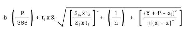
where
- b = slope of regression in μV/V per year for the regression data
- S 1 = standard deviation about the regression (SDEV) for the regression data
- S ra = SDEV of data filtered with 7-day moving average filter (MAF)
- P = period of time under consideration in days
- x̄ = mean of the time for the regression data
- n = number of periods in the regression data (e.g. 180 = 2 periods per day for 90 days)
- X j = jth period
- X 1 = time at beginning of the regression data
- t 1 = student’s t statistic for (n-2) degrees of freedom (typically 2.6)
- t 2 = student’s t statistic for [{n/(7 days)} - 2] degrees of freedom (typically 2.81)
In order to reduce 0.01 Hz to 10 Hz noise affects for this regression analysis, each data point for the computation of the regression parameters is usually the average voltage of about 50 readings taken in a 50-second measurement period.
If additional calibrations are performed on an instrument, noise specifications that are specific to that instrument can be computed, and then more accurate stability predictions can be made for the instrument outputs. In this case, b, S1 and Sra values specific to each output would be developed for an instrument that could then be utilized in the above stability prediction equation.
Wider temperature ranges, altitude changes, and humidity changes will affect an instrument, requiring that uncertainties for these effects be included in the above output voltage prediction equation. The paper listed below plus others can help with properly including needed uncertainties.
Output drift
Many instrument outputs drift nearly linearly over long periods, and so a linear regression fits the output voltage long-term time stability behavior very well. However, some have drift rates that are non-linear, especially earlier in their history. It is often possible to linearize the relationship between an output and time by transforming the time variable using transformations such as x’ = log (x-d) or x’ = sqrt (x-d), where d is a number corresponding to a date. This often leads to much lower uncertainty for the regression of output voltage versus time. The paper “Predicting 10 V dc Reference Standard Output Voltage” by Raymond D. Kletke found in the 1998 NCSL Conference and Symposium, pp. 615-621 and other papers can help with this approach.
Re-trace specifications
For optimum performance, the core voltage reference circuitry is maintained at a controlled, higher temperature by heater elements and control circuitry. If battery power is lost, the heated circuitry will cool off, and as a result of the laws of physics the voltage reference element may change voltage temporarily or permanently. If the temperature that the voltage reference cools off to is in the range of 23 °C to 35 °C, and the power off time period is up to several days, then the amount of shift in the 10 V output will be no more than that given in the Retrace Error table for the time off period. For example, if the instrument is left without ac power long enough that the internal battery discharges and the internal circuitry cools off to a 23 °C room temperature for three days, then the 10 V output would incur a maximum error of 0.25 μV/V or 2.5 μV. This resulting retrace (hysteresis) error is added (linear) to the Stability spec to obtain total uncertainty. Typically, the instrument long-term drift rate (slope) will not change for conditions within those specified for retrace error.
 在线客服
在线客服